Why the 4th pin? That’s MIDI DIN Out.
oh i thought the 4th was ground
sorry what i meant was 7th and 8th pin…not sure where i got 4th from
When you say “I’m not getting anything out of the USB Type B” what do you mean exactly? How does your DIY LED light connect to the USB port? Have you probed the pins on the port with a multimeter?
@kamil Id really like use the USB port to connect internally to my usb port on the teensy on my o&c running hemisphere. They have a great MIDI to CV and CV to MIDI app.
I was thinking of soldering jumper wires to the teensy directly then connecting them to the header on the midi pcb.
Which pins do I connect to?
Thanks!!!
Check out the schematic in Connect Pam’s to MIDI out on 7U case?
Pins 7, 8, 9, and 10 connect to the corresponding pins on the USB connector.
2 Likes
Excellent! i thought so but wanted to make sure. THANKS!!!
If you guys look for a smarter solution, scroll to the end of this thread:
Bumping this one.
I´m fairly new to the modular world, and just bought a truckload of stuff (Intellijel mostly) to get started.
I´m gonna install a Michigan Synth Works 16 fader bank. How do I go from these 4 pins to the MIDI out on my 7U performance case?
Best regards Pekka
MIDI Out Header: This is a 4 pin header but only 3 or 2 connections need to be used. To connect to a DIN cable, either GND, 5 (to pin 5, current sink/aka -), and 4 (to pin 4, current source/aka +) should be used. For internal module to module connections, only pin 4 and 5 should be used. The ground pin is only for the shield in a midi cable, it is never connected on a midi input and isnt necessary for the short module to module lengths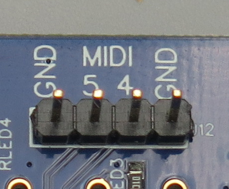
Having another look at the 7U pin header, it looks like you would connect the top 2 pins (1&2 which give you MIDI 4&4 respectively), then pin 7 provides GND. I’ll repost it below since it’s relevant.
Thanks, Scott! I´ll dig into this then.
First item on menu: Try to find the right cable at RS Online, among the millions of cables they have 
Hi there,
I’m pretty new to modular and had a couple of questions for you.
What cables did you use, and where did you order them from? As I’d love to wire my Pam’s NW to the MIDI on my 7U case.
And does this wiring scheme also connect to the USB MIDI on the Intellijel 7U case?
Thanks in advance,
Phil
1 Like
Hope it’s ok to bump this thread: 1U XY <> 7U case MIDI?
Wondering if I can use the XY IO 1u tile to hook into the 7U midi IO, and thus get TRS MIDI on the front of the case.
There seem to be an increasing number of modules with MIDI TRS so it would be super handy to have TRS ports on the case front that connect to the MIDI jacks on the case back.
It seems like it just needs a couple of jumper cables to do it.
MIDI Type A T,R,S corresponds to MIDI pins 5,4,2 respectively
MIDI Type B T,R,S corresponds to MIDI pins 4,5,2 respectively
On the 1U XY:
- X T,R,S connects to its JP1 pins 1,3,2 respectively
- Y T,R,S connects to its JP3 pins 1,3,2 respectively
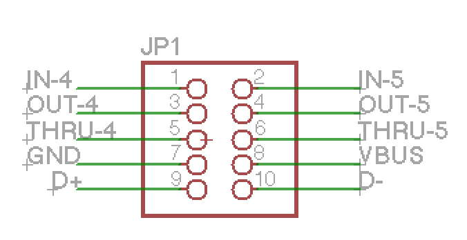
The JP1 on the case has 10 pins, for IN4/5, OUT4/5, THRU4/5, GND, VBUS, D+, D-.
So it seems pretty clear that I could hook the XY JP1 pins1/3 to IN4/5 (for type B) or IN5/4 (for type A); but should I then hook XY JP1/3 pin 2’s to GND on the case JP1? Or somewhere else? Or leave them unconnected?
Thanks for any help!
Hello dear all,
The same question with the Palette Case
Thanks
The Palette case uses the same 10-Pin MIDI header, so anything that applies to the 7U connector would work for the Palette.
Howdy folks. This is a great thread, and I’m hoping to do this myself as well, but seeing the photos have elicited a couple of (hopefully) quick questions.
Looking at the MIDI board in my 7u case, the 10-pin header is the same header that my uMIDI 1u connects to, which prohibits the addition of any additional jumper wires. Does this mean that I will need to remove the 10-pin cable that connects the uMIDI 1u to this board, and instead (a) use jumper wires to connect the three pins on the Pam expander to the proper three pins on the case’s board’s MIDI header, and (b) use jumper wires for the remaining five pins to connect the uMIDI 1u to the MIDI board?
Also, in the photos, it looks like the MIDI board is (when looking down from above) on the right side of the case, while mine is on the left. (Also, on my MIDI board, the header is shrouded, while this one isn’t.) I presume this is just a minor detail, such a difference in case versions, and that otherwise they’re the process is the same (namely header pinout). Is this correct?
Thanks for any help.
Have the same question as megarat. I have the uMIDI 1u and ideally want to connect both that and Pam’s expander simultaneously to the MIDI jacks. Given the Pam’s expander would take up the ground pin, does this mean you can’t have both?
You’d have to split the GND connection somehow, like soldering two wires together or using an intermediate 3 pin header.
Hi @ScottMFR - Is this pinout the same on the 1U Midi Jacks module? I’d like to connect it to Pam’s via the PEXP-2 expander as noted above by Armstrb.
I believe µMIDI 1U and MIDI 1U have the same MIDI pinout configuration, but @kamil can confirm that.
1 Like