Yes it should be possible. Just check out the schematic of the pinout in the thread @exper linked.
Hi Kamil
Hoping you can help me connect things the right way. I’ve been in contact with the ALM Busy Circuits and come to the conclusion that the easiest way to do this was off the PEXP-2 header. It has three pins as follows:
Pin 1 = 5V
Pin 2 = GND
Pin 3 = MIDI TX (leveled and buffered)
If I wanted to connect this to the 7U cases MIDI out port, which pins do I connect to on the J1 header?
I would assume that
Pam’s Pin 3 -> IJ Pin 3
Pam’s Pin 2 -> IJ Pin 4
Pam’s Pin 1 -> ? (Maybe Pin 8?)
Thanks in advance
Ben
Just leave it unconnected. Connecting it to pin 8 will send it to the USB port VBUS, which is probably not what you want.
Got it. So you don’t use the 5V at all?
I thought that was part of the standard?
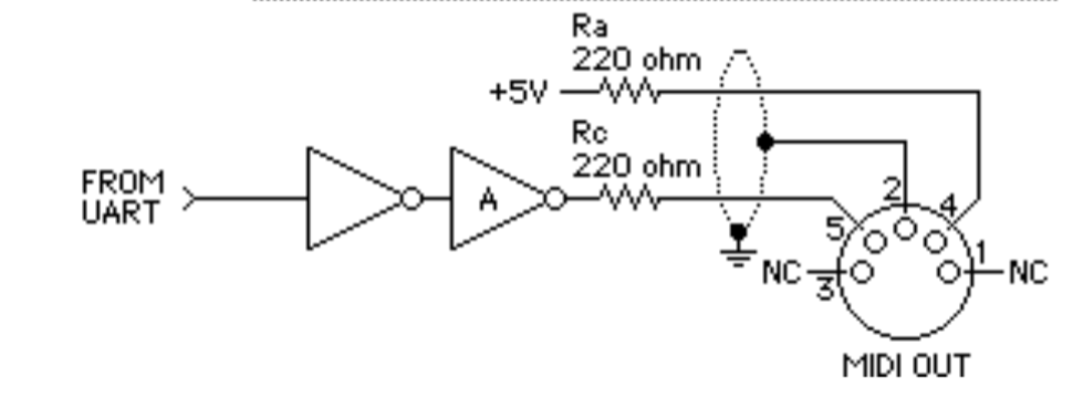
Sorry, answered still early in the morning  OUT-4 goes to pin 4 of the DIN connector and OUT-5 goes to pin 5. In a MIDI out you usually connect the TX to pin 5 of the connector, and 5V through a 220Ω resistor to pin 4.
Here’s a diagram from the MIDI 1.0 spec:
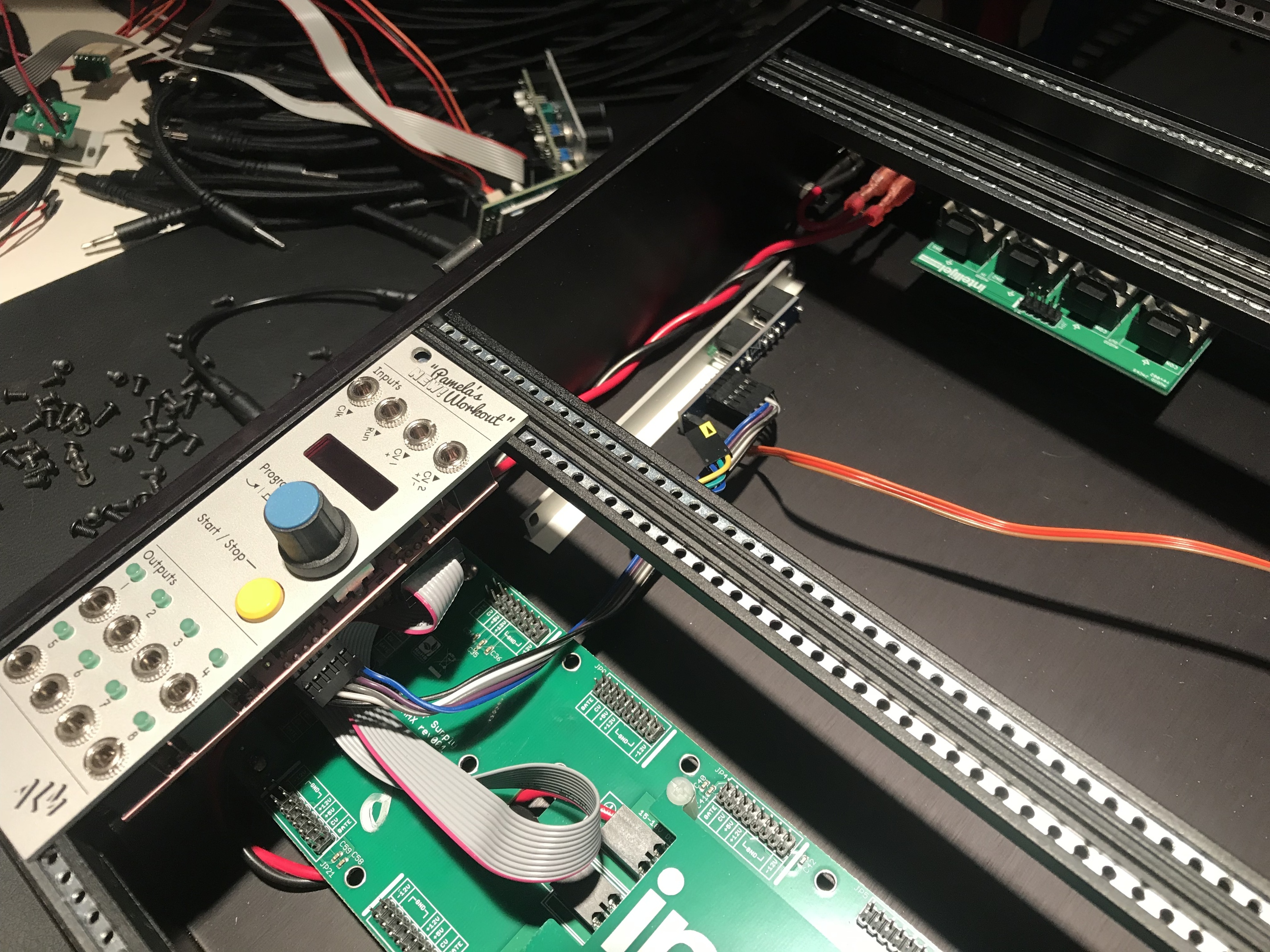
OK, so given this is the header on the case:
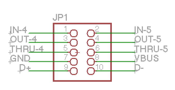
Am configuring as follows
PEXP-2 Pin 1 (5V) -> IJ J1 Pin 3 (DIN4)
PEXP-2 Pin 2 (GND -> IJ J1 Pin 7 (GND/ DIN2)
PEXP-2 Pin 3 (MIDI TX) -> IJ Pin 4 (DIN5)
3 Likes
Yes that seems like it should work. Though I’m not sure if you need to add 220Ω resistors or if the pams has them already.
They do on the PEXP-2 header that’s what am using that and not the one on Pam’s itself.
Will do.
@kamil - want to confirm that Pin 1/ 2 is the side of the header on JP1 marked with the white bar. Is that correct?
Yes that should be the case
This is brilliant
I’d love to see the finished concept in use, and also a little bit of a step by step with pics for how you did this. Pamela’s New Workout sending midi clock out of the 7U case would be a serious win all around. Clocking from the mother box, and not the other way around. I love it. I want it. I need it.
2 Likes
I’ll be trying it over the weekend now Kamil has confirmed the pin orientation.
2 Likes
so… any updates? 
Got this all working.

Am now trying to persuade Erica Synths to put a clock signal on the header they have on the back of the Drum Sequencer so could do it with that too.
5 Likes
Hi Kamil this is a somewhat related question. Is it possible to power the USB type B port on the back of the 7U case using a split i2c cable from the 2 +5V pins on the bus to the JP1? It’s to power a DIY’d LED light. I see that GND is the 7th pin but can’t figure out where the 5V pin would be for that particular port (if there is one). Unfortunately all my 1U space is taken otherwise I’d go for the 1U usb.
Thanks for your help.
Pin 8 (VBUS) is connected to the USB port’s power pin.
I connected 2 female to female breadboard style cables from the 5v on the psu to the 4th and 8th pin but i’m not getting anything out of the usb type b. wondering if the midi on my case might be faulty?
Why the 4th pin? That’s MIDI DIN Out.
oh i thought the 4th was ground