Will do.
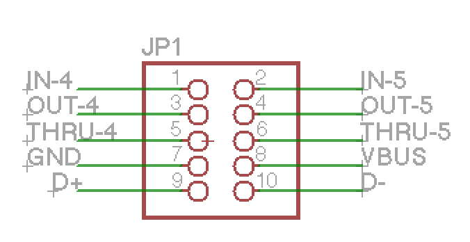
@kamil - want to confirm that Pin 1/ 2 is the side of the header on JP1 marked with the white bar. Is that correct?
Will do.
@kamil - want to confirm that Pin 1/ 2 is the side of the header on JP1 marked with the white bar. Is that correct?
Yes that should be the case
This is brilliant
I’d love to see the finished concept in use, and also a little bit of a step by step with pics for how you did this. Pamela’s New Workout sending midi clock out of the 7U case would be a serious win all around. Clocking from the mother box, and not the other way around. I love it. I want it. I need it.
I’ll be trying it over the weekend now Kamil has confirmed the pin orientation.
so… any updates? 
Got this all working.
Am now trying to persuade Erica Synths to put a clock signal on the header they have on the back of the Drum Sequencer so could do it with that too.
Hi Kamil this is a somewhat related question. Is it possible to power the USB type B port on the back of the 7U case using a split i2c cable from the 2 +5V pins on the bus to the JP1? It’s to power a DIY’d LED light. I see that GND is the 7th pin but can’t figure out where the 5V pin would be for that particular port (if there is one). Unfortunately all my 1U space is taken otherwise I’d go for the 1U usb.
Thanks for your help.
Pin 8 (VBUS) is connected to the USB port’s power pin.
I connected 2 female to female breadboard style cables from the 5v on the psu to the 4th and 8th pin but i’m not getting anything out of the usb type b. wondering if the midi on my case might be faulty?
Why the 4th pin? That’s MIDI DIN Out.
oh i thought the 4th was ground
sorry what i meant was 7th and 8th pin…not sure where i got 4th from
When you say “I’m not getting anything out of the USB Type B” what do you mean exactly? How does your DIY LED light connect to the USB port? Have you probed the pins on the port with a multimeter?
@kamil Id really like use the USB port to connect internally to my usb port on the teensy on my o&c running hemisphere. They have a great MIDI to CV and CV to MIDI app.
I was thinking of soldering jumper wires to the teensy directly then connecting them to the header on the midi pcb.
Which pins do I connect to?
Thanks!!!
Check out the schematic in Connect Pam’s to MIDI out on 7U case?
Pins 7, 8, 9, and 10 connect to the corresponding pins on the USB connector.
Excellent! i thought so but wanted to make sure. THANKS!!!
If you guys look for a smarter solution, scroll to the end of this thread:
Bumping this one.
I´m fairly new to the modular world, and just bought a truckload of stuff (Intellijel mostly) to get started.
I´m gonna install a Michigan Synth Works 16 fader bank. How do I go from these 4 pins to the MIDI out on my 7U performance case?
Best regards Pekka
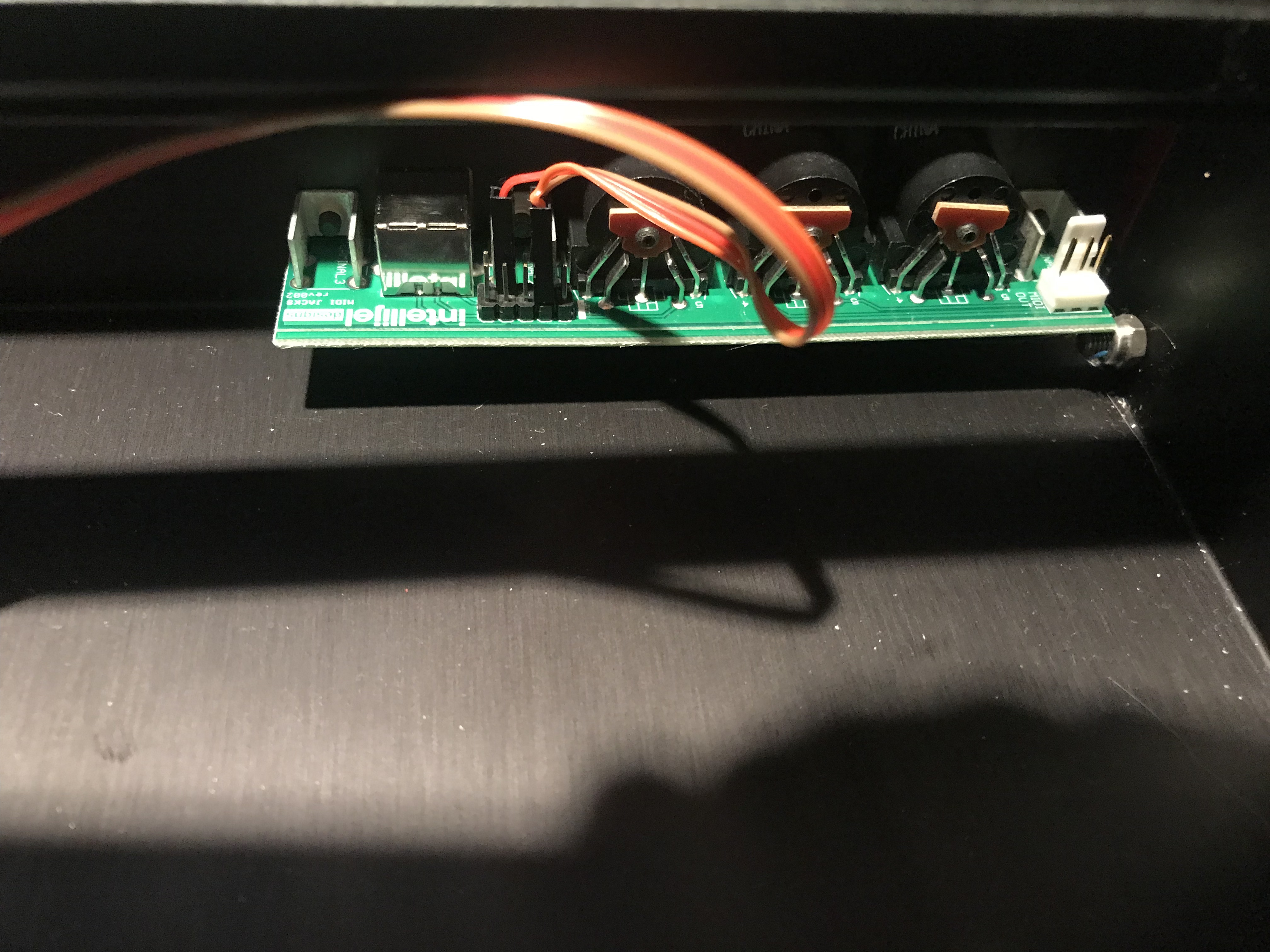
MIDI Out Header: This is a 4 pin header but only 3 or 2 connections need to be used. To connect to a DIN cable, either GND, 5 (to pin 5, current sink/aka -), and 4 (to pin 4, current source/aka +) should be used. For internal module to module connections, only pin 4 and 5 should be used. The ground pin is only for the shield in a midi cable, it is never connected on a midi input and isnt necessary for the short module to module lengths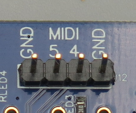
Having another look at the 7U pin header, it looks like you would connect the top 2 pins (1&2 which give you MIDI 4&4 respectively), then pin 7 provides GND. I’ll repost it below since it’s relevant.
Thanks, Scott! I´ll dig into this then.
First item on menu: Try to find the right cable at RS Online, among the millions of cables they have