Wondering if I can use the XY IO 1u tile to hook into the 7U midi IO, and thus get TRS MIDI on the front of the case.
There seem to be an increasing number of modules with MIDI TRS so it would be super handy to have TRS ports on the case front that connect to the MIDI jacks on the case back.
It seems like it just needs a couple of jumper cables to do it.
MIDI Type A T,R,S corresponds to MIDI pins 5,4,2 respectively
MIDI Type B T,R,S corresponds to MIDI pins 4,5,2 respectively
On the 1U XY:
X T,R,S connects to its JP1 pins 1,3,2 respectively
Y T,R,S connects to its JP3 pins 1,3,2 respectively
The JP1 on the case has 10 pins, for IN4/5, OUT4/5, THRU4/5, GND, VBUS, D+, D-.
So it seems pretty clear that I could hook the XY JP1 pins1/3 to IN4/5 (for type B) or IN5/4 (for type A); but should I then hook XY JP1/3 pin 2’s to GND on the case JP1? Or somewhere else? Or leave them unconnected?
Howdy folks. This is a great thread, and I’m hoping to do this myself as well, but seeing the photos have elicited a couple of (hopefully) quick questions.
Looking at the MIDI board in my 7u case, the 10-pin header is the same header that my uMIDI 1u connects to, which prohibits the addition of any additional jumper wires. Does this mean that I will need to remove the 10-pin cable that connects the uMIDI 1u to this board, and instead (a) use jumper wires to connect the three pins on the Pam expander to the proper three pins on the case’s board’s MIDI header, and (b) use jumper wires for the remaining five pins to connect the uMIDI 1u to the MIDI board?
Also, in the photos, it looks like the MIDI board is (when looking down from above) on the right side of the case, while mine is on the left. (Also, on my MIDI board, the header is shrouded, while this one isn’t.) I presume this is just a minor detail, such a difference in case versions, and that otherwise they’re the process is the same (namely header pinout). Is this correct?
Have the same question as megarat. I have the uMIDI 1u and ideally want to connect both that and Pam’s expander simultaneously to the MIDI jacks. Given the Pam’s expander would take up the ground pin, does this mean you can’t have both?
Hey Scott, My 7U case has the MIDI pins right on the circuit board and not in a keyed enclosure. Are the pins beside the white line on the circuit board 1 & 2 or 9 & 10?
Thanks Scott, but I still need to confirm if the pins beside the white line on the circuit board are 1 & 2 or 9 & 10. ??? The white line is on the right when I’m looking down on it from the front.
I’ve been trying to connect a Disting EX to the MIDI ports and have not had any success in making it work yet.
I bought a little test meter and was able to confirm that the white line on the circuit board is beside 1 & 2 in the diagram. My Disting EX is now MIDIfied!
Has anybody thought of modifying the Befaco CV Thing to connect to the Midi Out?
They have the schematics on their website, but sadly its expander out doesn’t carry any midi signal.
Just thinking about the possibilities, maybe you could solder 3 jumper cables directly onto the trs jack pins and connect it directly to the midi out?
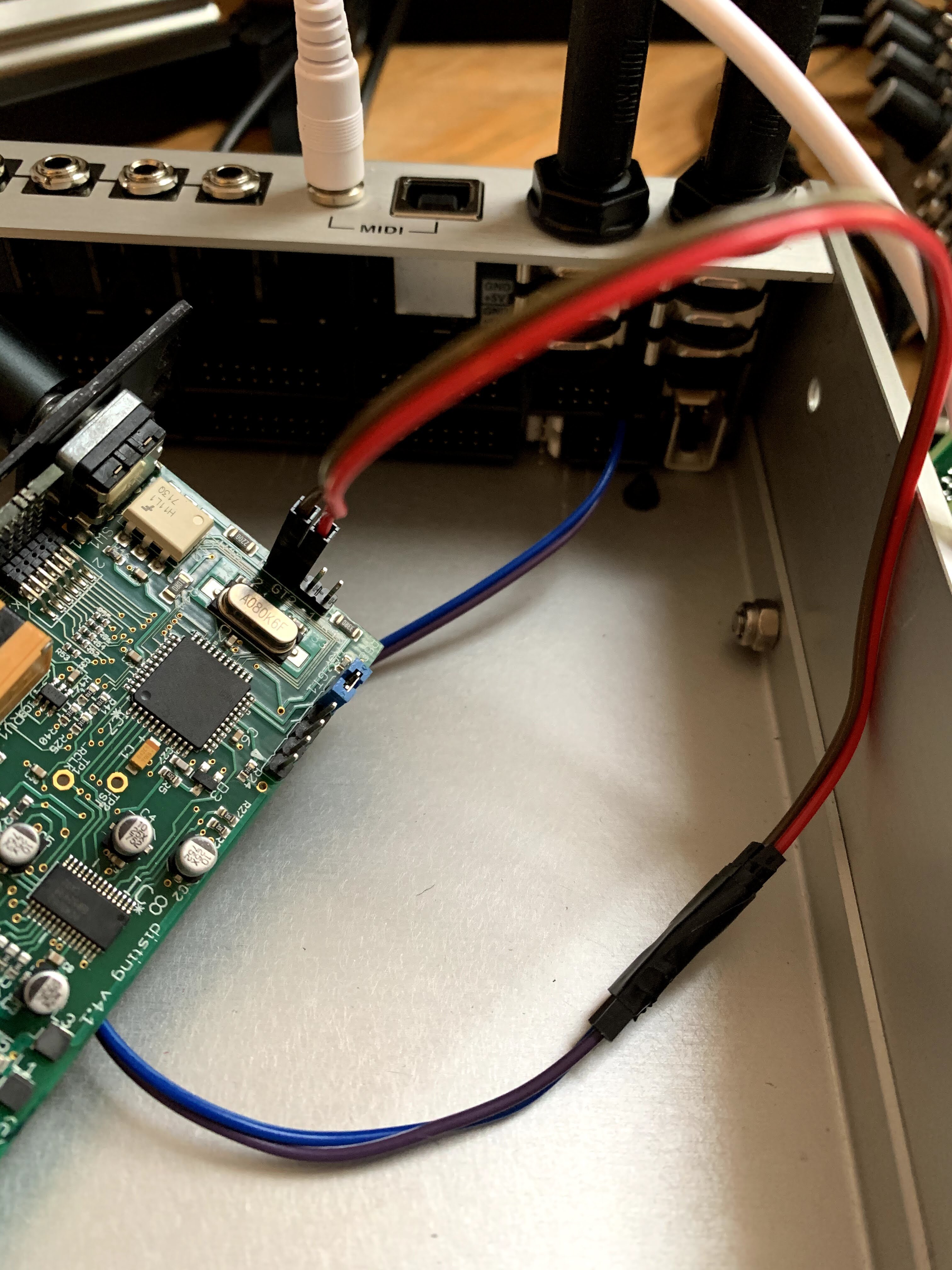
I have successfully connected my Disting Mk4 to the MIDI IN on my 62hp Palette case. I can only share one photo at a time but hopefully this is helpful ~ it seems to be working perfectly.
I was considering buying a Digitakt if I could easily clock the modular so now I feel okay doing it. Also, Disting can be useful for other stuff if you don’t need a clock so that’s a plus.