As I mentioned I’m no expert so someone else might have a better way. I measured, measured again, and measured again to be sure. Once I had my spot, I used an awl to make a dent. Was super careful to get the dent in the right spot. Then I used a very small bit to drill a pilot hole, then a bigger bit to make the final hole. Shards of aluminum were made in the process, wear some eye protection.
2 Likes
What kind of drills did you use? What surface did you put the aluminum sides on and how did you fixate them?
I used a standard Milwaukee hand drill and regular drill bits, nothing special. Aluminum is soft so it drills quite easily. I did not remove the sides to do this, I simply turned the case on it’s side resting on my rug and drilled downward.
I should probably say again that I am not an expert in this area  There is probably a better way to do this but I was successful twice using this hack.
2 Likes
I would use a wood backer so it doesn’t punch through and damage anything!
There is a bit called a center drill that has a small tip and then a 60 degree angle which will make a starting place for a regular drill bit so that it can not wander when starting your hole.
Small center drills (1/4") are perfect for following a center punch mark in Aluminum.
Foghorn
a machinist (for 50 years)
4 Likes
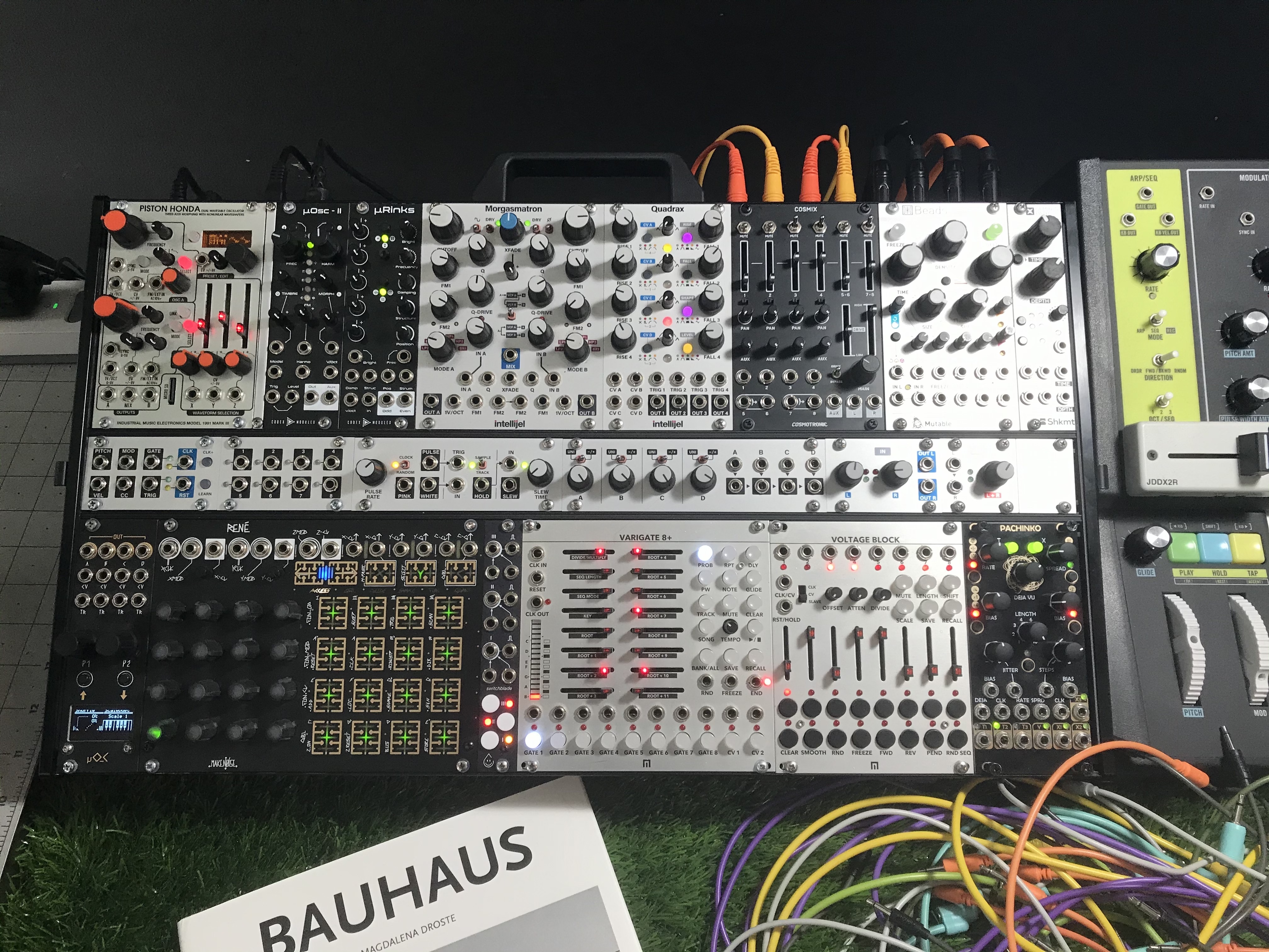
This is pretty easy to do. Use a pencil or marker and a 5/32” drill bit and M4 round head screws. It took me 5 hours to remove everything, move the 1u row, install the modules and repatch. Worth it. Intellijel, if you add a hole and extra screw to the case, users could do this when they first buy the case. Should be easy to change manufacturing and add two holes. Having utility at the top of the case creates too much cable clutter.
5 Likes
Extra screws wouldn’t even be necessary, as you could just move the screws with the rail. It would leave a hole on each side, but covering the hole with a screw would get in the way of whatever modules are at the ends, unless it was extra-short and only used to cover the hole.
One potential problem is that the ports reduce the available depth of a large portion of the top 3U row. It probably isn’t a big deal, unless you own a lot of Doepfer modules or something.
Having the case come with the extra two holes would mean they’d be nicely countersunk too.
1 Like
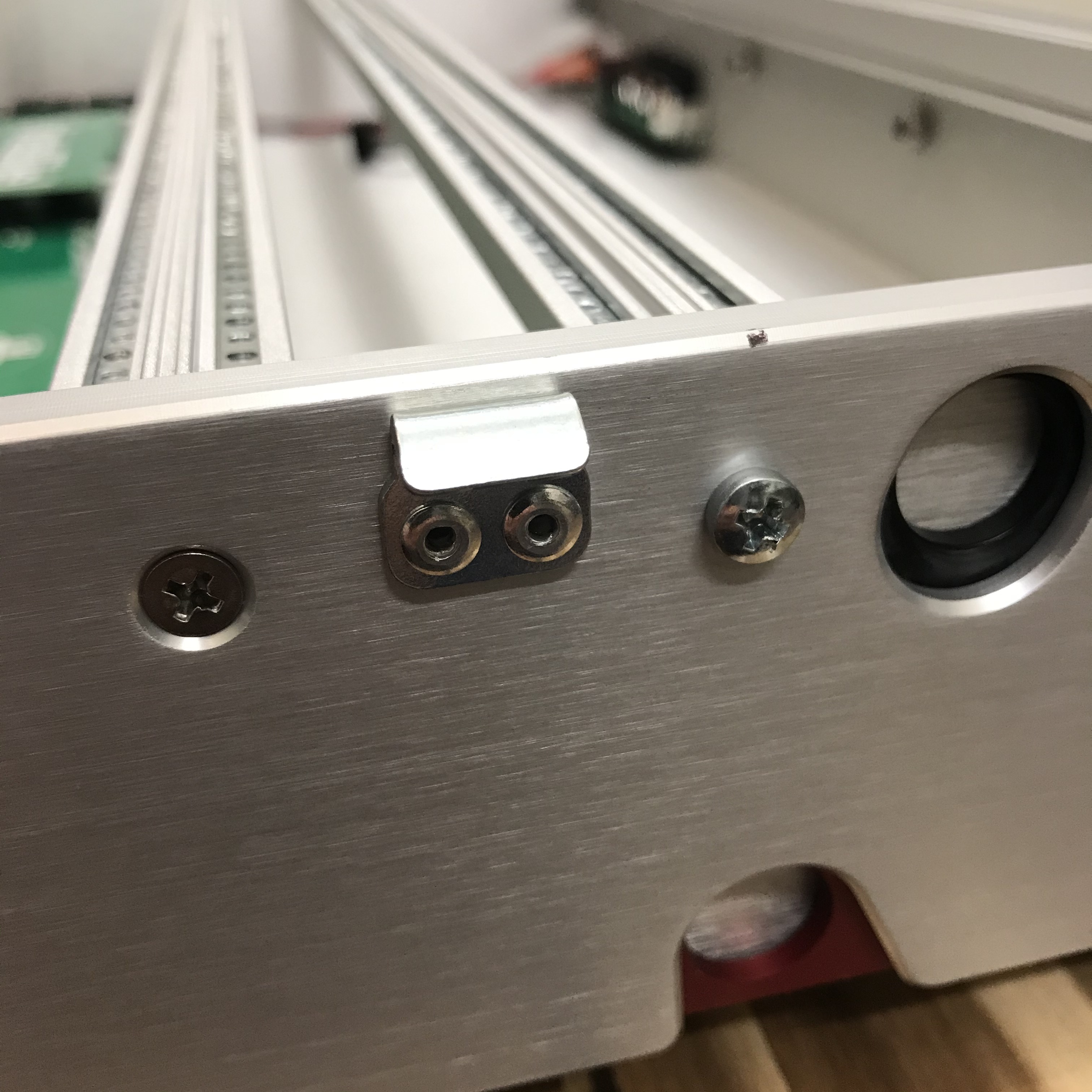
I was considering doing this mod on one of my 7u cases, but I’m a little unclear on how y’all are dealing with the bottom rail of the top 3u row… from the pics, it seems like you aren’t drilling a hole for it (because it would seem to go where the latch trigger is for the stand leg). Is that rail just kinda floating? how does that work?
The rails are joined into a single piece. If you take one of them out you’ll see right away. One screw on each side of the case holds the pair of rails in place. Makes the process that much easier!
2 Likes
thanks for the info! 
@davidjames ok sadly that is not actually the case with mine. i guess they changed the design after the initial version. looking at the photos on their website, it’s different. I have a screw for each rail on mine and in the current version i can see how there is one screw for the pair 
I haven’t seen that version so I can’t say for sure if drilling two holes would work. If not, maybe you could source a newer rail assembly and use that instead? It’s early and I haven’t had my coffee yet so hopefully that makes sense
If someone is going to do this adjustment, it would be very much appreciated if you could take some photos for each step of the process. I want to do this but I’m a bit too scared of messing it up without very clear instructions
1 Like
Also successfully performed this modification today. It’s quite straight forward. As others have suggested, make sure you measure as many times you need until you’re confident. Mount some modules or blanks to get a good fit too. I didn’t have an awl so used a nail and hammer to make an indentation. Then I used a standard 1mm drill bit to drill the pilot hole, I couldn’t jump straight to 4mm so used a 3mm between. I placed the case side down and drilled outside, in. I hadn’t drilled alu before, took a minute to get used to, high speed in pulses seemed to work well. I also managed to shake loose most of the PSU fixings, but easy to fix if you have the right hex size. PM me if you need any help, took me a few hours in total but 100% worth it, patches are much more ergonomic now.
2 Likes
Exactly what Intellijel should do: Providing the necessary holes so users can change easily.
2 Likes
Ahhhhh, much better. Added another Audio jacks board and a USB power jack to the back while I was at it:
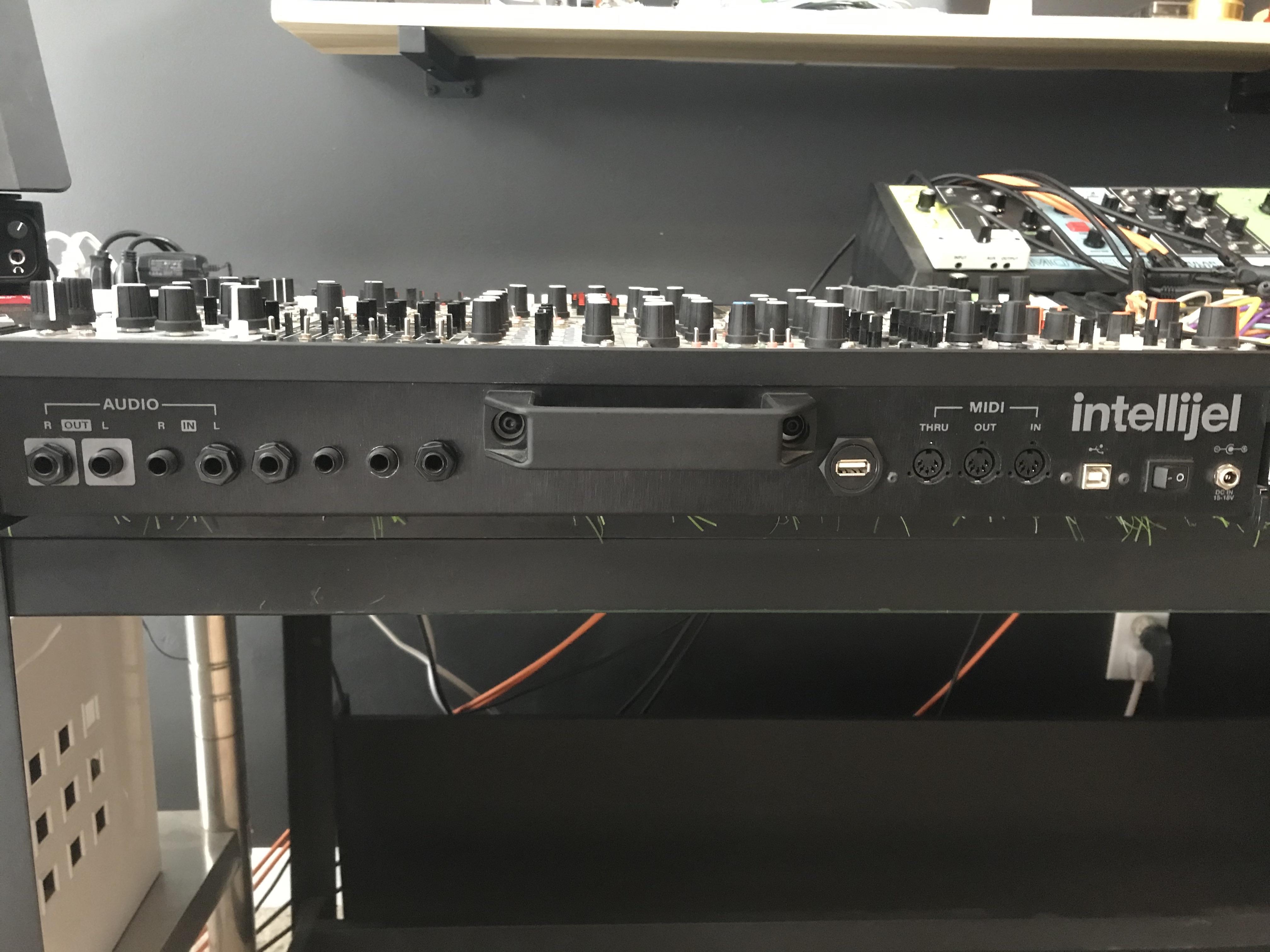
9 Likes
Wow, deluxe!
2 Likes
this would be such a simple thing to add to the cnc program, adding probably less than a minute to fabrication time and the only thing it would add to the BOM is a rubber plug to cover the hole not being used, intellijel should really consider doing this.
For you guys that have modded this, one thing you could do to cover the hole is tap it w threads and then just screw in a 3/16" bolt to cover the hole and it’ll look perfect.
2 Likes
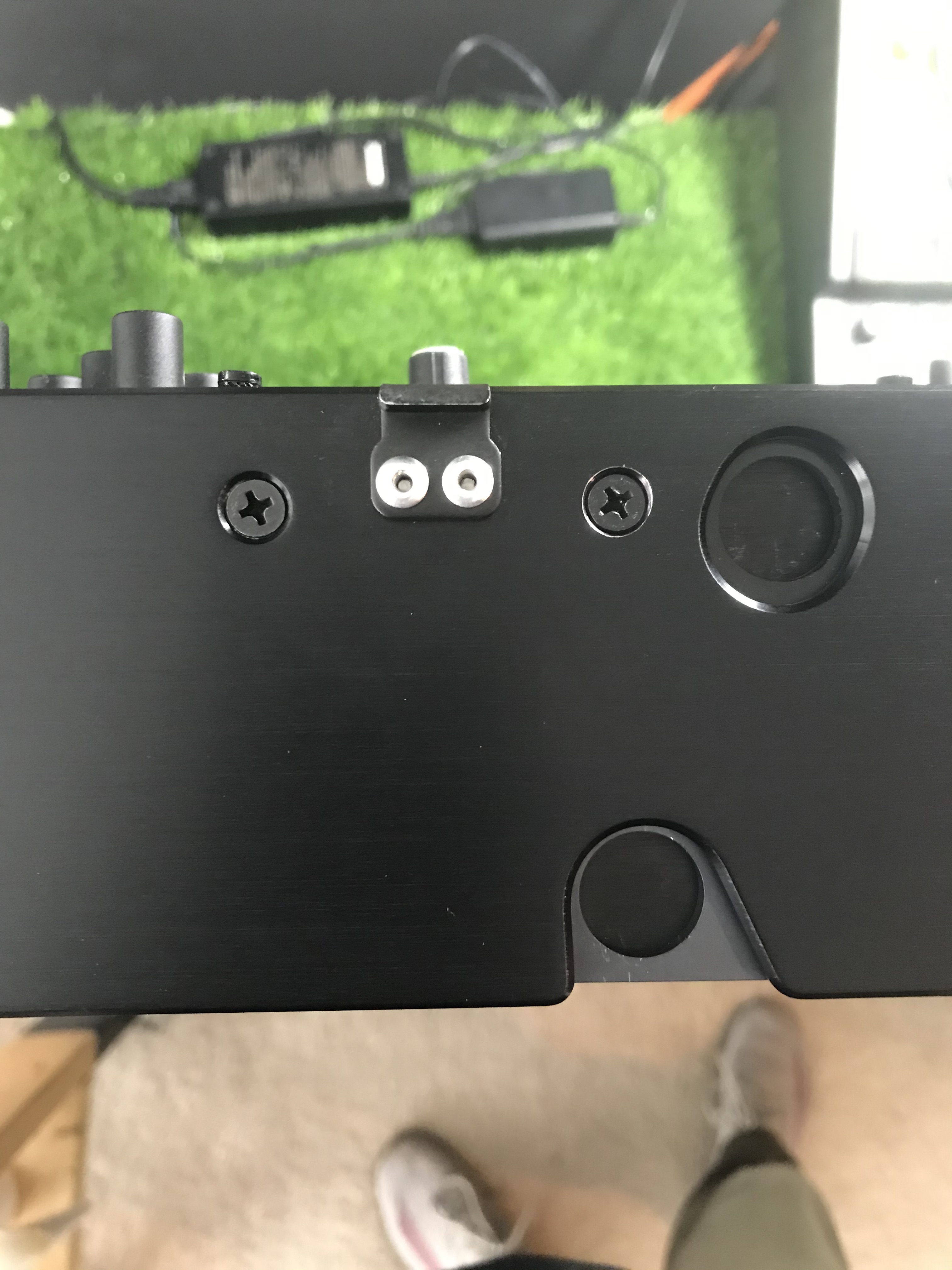
Did this modification interfere with the latching feet at all? The latch seems awefully close to the part where you need to drill. Considering doing this modification to my case.
Thanks! 