Sounds really good! thanks for sharing 
1 Like
I did some messing around as well, using Bifold in stereo. The patch starts rather abstract and evolves into a stable sequence about half-way through. I still can’t get over the glorious timbres I’m getting out of this thing. Its ability to provide surprises that always remain musical makes it an amazing experimentation pal.
- Ts-L sine wave going to Bifold’s P input
- S and P inputs sent separately to Cold Mac Left+Right inputs for stereo crossfading
- Mostly X mode, with some manual switch to SYM at some point
- Quadrax modulating the crossfader and P and S (very slow LFO for subtle yet ever evolving waveform)
- Mimeophon with a lot of semi-randomization of params
A bit of filtered noise waves and René for sequencing. Hopefully it’s an interesting demonstration of the kind of timbres the module can provide.
5 Likes
Sounds great! A lot of subtlety there
Thanks! René is actually being clocked by Steppy, so it allows for a lot of freedom of how “full” you want your sequences to be, it’s great for on the fly control over the evolution of your sequences.
Yeah, modulating the X/Y of Rene with a two-channel step sequencer was a technique I employed for a long time. I used to use Monome Meadowphysics for that back in the day, but Steppy would be a great option too.
1 Like
Hello, Intellijel community! I have been lurking here and in MW for a few months now, I’m relatively new to modular, and I think it’s finally time for my first post/question:
I’m having trouble understanding how the Bifold achieves ring modulation. I understand that the instructions say to send a carrier signal to input P and invert the carrier on “channel S”, then send a modulator to the XFADE input and set the XFADE attenuverter to fully clockwise. I don’t have the Bifold yet, so I’m trying to model this in VCV Rack with an inverter and a crossfade module (made by Bogaudio). Depending on where I set the crossfader knob, I can get something that sounds like “true” ring modulation, but when I look at a spectrum analyzer, the carrier is still present.
Can someone explain how this inversion-crossfade method is supposed to achieve ring modulation, and does anyone have any idea why I’m still seeing the carrier frequency in my VCV Rack patch?
EDIT: I think I understand why the carrier is still showing up, faintly: Because summing the carrier and its inverse isn’t cancelling it out perfectly. Not a big deal I suppose.
If you carefully adjust the xfade knob you should be able to get it to almost very perfect cancellation.
1 Like
The manual provides these instructions to achieve ring modulation (with a couple details omitted):
- Plug a signal into IN P. (With nothing plugged into IN S, the signal from IN P is passed to the Serial channel.)
- Invert the phase of the Serial channel.
- Balance the crossfade knob so the Parallel and Serial channels cancel each other.
- Plug your modulating signal into XFADE and turn the XFADE attenuverter knob fully clockwise.
The manual also says:
When the value of the XFADE knob and the attenuverted XFADE inputs sums to zero (or a negative voltage), then only the Parallel channel feeds the crossfader. When the value of the XFADE knob and the attenuverted XFADE inputs sums to +5V, then only the Serial channel feeds the crossfader. Summed voltages between 0V and 5V create a blend of the two channels.
What if you use a bipolar modulating signal? When you turn the XFADE attenuverter fully clockwise, aren’t you passing both the positive and negative values of the modulator? I think I’m misunderstanding what value the mix out reads from the XFADE knob in this configuration, because I keep thinking it’s reading zero since the two signals on the Parallel and Serial channels are cancelling each other, and with a bipolar modulator, it seems that the crossfader would be stuck on the Parallel channel whenever the modulator’s voltage is negative…?
1 Like
There’s another potential problem I thought of: Let’s say the XFADE knob reads “2.5V” when centered, so even when the modulator goes negative, the sum of the XFADE knob and attenuverted XFADE input is still between 0-2.5V. That would mean the XFADE knob would do a clean sweep. But if a negative modulator is multiplying with the inverse of the carrier, I could be wrong but I don’t think that generates ring modulation that will eliminate the carrier frequency…?
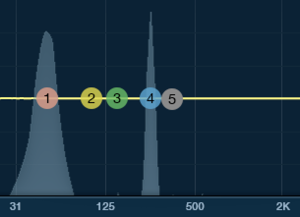
In the following images I have a 100 Hz sine modulator and 150 Hz sine carrier. Here is ring modulation:
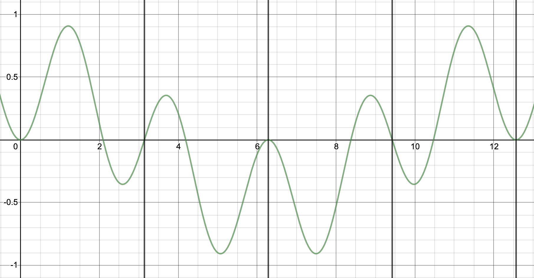
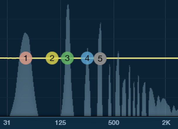
And here what I believe this crossfading method would generate:

Very curious to hear more, Intellijel!
Ring modding is just xfading a signal with its inverse.
With Xfade knob in perfect center, the two sides cancel out. At full CW you get inverted signal %100 and full CCW you get normal signal 100%.
Put your modulator in XFADE control and turn up attenuator to full (while XFADE knob is in middle). Now your bipolar source modualting the carrier to 100% positive or 100% negative. This is ring modding.
So just to be clear: you carrier is going to IN P and IN S via normalling, the modulator goes to to CV input. We are expecting the modulator to be bipolar.
EDIT: if it is a typical modular waveform of +/-5V (like from a VCO) then you adjust the XFADE attenuator so that the modulator is half it’s amplitude. This would produce a modulation of -2.5V to +2.5V which is what you need to move the XFADE control from the center position to full CCW and full CW
2 Likes
Ok, I know what I was getting hung up on now: I kept thinking that the modulator voltage was multiplying with the voltage of the signal being sent from the Xfade knob, it’s not. The modulator voltage is simply controlling the position of the Xfade knob.
My only other question would be about this comment in the manual:
How is there never a negative sum if the modulator is bipolar? It would appear that whenever the modular voltage is negative, say, -a, that the “Xfade voltage” would need to be greater than or equal to a to stay nonnegative. 
I forgot an important detail and edited my reply above. You need to attenuate your bipolar modulator to 50% of it’s value use the attenuverter control on the Bifold. So XFADE control in center position is equivalent to 2.5V (The knob range is 0-5V). Adding 2.5V pushes it to full CW, subtracting 2.5V pushes it to full CCW.
The resulting MIX output will be +/-5V (full range).
Also yes it is possible to get a negative sum, but at 0V the VCA is off and anything below is still “off”.
1 Like
Ok, now I’m 100% on board. I was confused about what voltage was being passed from the Xfade knob depending on its position. So 0 to 5 with 2.5 being in the middle, then if your modulator is ±2.5, it’s always hitting between 0 and 5 (it may drop slightly below 0 on the sweep CCW or slightly above 5 on the sweep CW, but if you get the balance right it should be negligible).
The manual also says:
Patch a second oscillator into the XFADE [I] CV input and set the XFADE [15] attenuverter fully positive (clockwise).
If the summed voltage is going above 5 or below 0 periodically, I wonder if it will still cancel the carrier as effectively. Now I know to aim for ±2.5 so I guess it doesn’t really matter…will be fun to do some tests when I get my own Bifold. 
Thank you for your help, Danjel!
I notice that in order to push the wavefolder to its final stage, you need +10v DC offset, but the attenuator is only +5v. Also, the harmonics can be shifted even further by roughly a fifth interval with the fold knob and a +10v offset input. What is the design intention for that?
I found that rather weird that each knob have a different DC offset value and you can shift the harmonics even further with the fold knob. May be the attenuator is more for fine tuning purpose?
The fold knob’s design is rather uncommon too. Usually the fold knob should push the wavefolder to its final stage when it is full CW and add DC offset to the wavefolder to ‘open’ the wavefolder. However, you can shift harmonics even further when it its full CW ,with +10DC offset in the input.
Please let me know.
The “Fold” control is simply the CV for a linear VCA acting on your input signal that feeds the folding networks. So 0 is amplitude of zero, 5V is unity gain and 10V would be doubling your input signal. We have designed this module so that the range of 0-5V is the normal range we would expect to fold with. In this case “normal” means that a 10Vpp signal (e.g. sine wave straight from a Dixie) would be folded 6 times or very close to that. If your source signal is less than this, then it may require some extra boosting via the offsets but most Eurorack VCOs should be putting out 10Vpp.
As you increase the Fold control, you will see your source signal hit each breakpoint in the folder until it goes past the last one. At this point the two sides act a bit different but on the Buchla side you are simply continuing to amplify a signal to the point that it clips the rails and turns into a big, harsh square wave. That is not the final stage, it is beyond the final stage.
The buchla side also has a 1 pole low pas filter with a corner frequency of ~ 1kHz. This might seem really low but it makes a lot of sense when you think about what a folder is doing. If you started with 500Hz, every fold is doubling the frequency; so six folds would yield 500>1000>2000>4000>8000>16000>32000 (!) With a mild sloping filter you tame these super high frequencies and the fundamentals remain dominant. The serge side has a much higher cutoff in comparison and so it can give the impression of being brighter/buzzier but I have always found the Buchla folder to be more musically pleasing and useful.
I clearly show the fold knob with no use of attenuators going through all the fold stages at the beginning section of this video:
2 Likes
Hi Danjel,
Thanks for the detailed reply.
I checked the folded waveform in oscilloscope again.
With 10vpp sine wave and +10v envelope, Fold P outputs roughly 20vpp and Fold S output roughly 10vpp. It is indeed being overdrived further with peak and trough squared off. It might be wise to add a limiter / clipper after the wavefolder to limit the signal to 10vpp.
Good to know more about the design intent behind those folders.
Yeah, the Serge side is lot brighter and harsher, not as ‘wind pipe-y’ sound as described in Serge’s manual, but it is musical nonetheless. The Buchla one is more woody tonally. They have nice contrasts.
Just a note to say how much I like the Bifold. Quickly become my favourite wavefolder - both sides sound great and the extra features are really well thought out, making it super creative whether folding or not.
1 Like
Is it normal for the serial side to a fair bit louder than the parallel?
Know the S side is more aggressive than the other, in part due to the P’s LPF - but the volume, when feeding just one signal into P with all other controls equal and symmetry on X, is significantly higher from S on my unit - as to be expected?
Particularly noticeable when using for stereo folding, can compensate somewhat with the other settings if it’s normal.
Cheers!
It’s frequency dependent. So with higher frequency signals >1khz), it will be louder on the S side relative to the P side. But also the two folders operate differently on certain wave shapes.
If you try a sine wave that is ~ 500Hz, they should be pretty equal in level from side to side. If they are not, then there may be an issue with your module.
Ok thanks, will give that a try when I unplug the current patch