Some people have expressed interest in integrating the Tetrapad with other I2C devices such as those made by Monome or Orthogonal Devices. Unfortunately we’re too busy with other projects here to be able to do such integrations ourselves so with that in mind I’m going to publish some info here that can help others do that. I’ll be monitoring this thread to answer any questions / provide additional information as needed.
Hardware Info
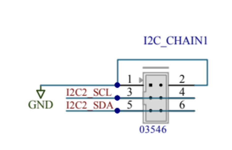
The I2C connectors on the Tetrapad are both the same, there are two to facilitate easy chaining between devices. The pinout is compatible with Monome’s ii bus:
The address of the Tetrapad is selected via the switches on the back of the module, allowing up to four Tetrapads to be used on one I2C bus. With both switches in the off (00) position the address is 0x3B. Using the switches it’s possible to set the address to 0x3C (01), 0x3D (10), or 0x3E (11).
The Tetrapad I2C interface works on a pretty typical request-response basis like most I2C devices.
Each command consists of an initial byte that identifies the specific command, then a variable number of bytes of data, depending on the command.
Commands
Here’s the available commands, posted as C++ code. I may massage these into a table later but hopefully this is clear enough.
enum class ID : uint8_t {
  ENABLE_HANDLER            = 0x00,
  DISABLE_HANDLER           = 0x01,
  READ_SENSORS              = 0x02,
  READ_UI                   = 0x03,
  SET_OUTPUTS               = 0x04,
  CLEAR_LEDS                = 0x06,
  SET_STATUS_LEDS           = 0x08,
  SET_SENSOR_LEDS           = 0x09,
  SET_STATUS_LEDS_6BIT      = 0x0a,
  SET_SENSOR_LEDS_2BIT      = 0x0b,
  SET_ENCODER_LEDS_6BIT     = 0x0c,
  SET_OUTPUT_LED_TYPES_4BIT = 0x0d,
  SET_SENSOR_SETTINGS       = 0x0e,
  READ_SENSOR_SETTINGS      = 0x0f,
  READ_VERSION              = 0xff,
};

struct Info {
  // Command ID.
  ID id;

  // Size of the request data, in bytes.
  size_t request_size;

  // Size of the response data, in bytes.
  size_t response_size;
};

namespace IJN = IJ::Numeric;

// Enable the I2C handler on the Tetrapad, disabling the native functionality.
// Tetrapad outputs and LEDs will be updated only via I2C requests.
constexpr auto ENABLE_HANDLER = Info{ID::ENABLE_HANDLER, 0, 1};

// Disable the I2C handler on the Tetrapad, re-enabling all native functionality.
constexpr auto DISABLE_HANDLER = Info{ID::DISABLE_HANDLER, 0, 1};

// Read the sensor values.
// The values are returned as two packed arrays of 12-bit numbers plus an 8-bit bitmask.
// The first array is the last-touched position of each sensor.
// The second array is the current pressure of each sensor.
// The bitmask indicates which sensors are currently being touched.
constexpr auto READ_SENSORS = Info{ID::READ_SENSORS, 0, IJN::Packed12BitSize(Constants::NUM_SENSORS * 2) + 1};

// Read the button and encoder states.
// The first byte contains a bitmask for the button states with the following fields:
// 0 - 3: Encoders
// 4: Shift (red button)
// 5: Config (white button)
// The next four bytes are the current position of the encoder, from 0-255.
constexpr auto READ_UI = Info{ID::READ_UI, 0, 5};

// Set the output values.
// Each output is 12-bit, with 0xfff / 2 being 0V.
constexpr auto SET_OUTPUTS = Info{ID::SET_OUTPUTS, IJN::Packed12BitSize(Constants::NUM_OUTPUTS), 0};

// Turn off all LEDs.
constexpr auto CLEAR_LEDS = Info{ID::CLEAR_LEDS, 0, 0};

// Set the output status LEDs.
// The data is an array of 8-bit values in R,G,B order for each LED.
// Using this command will revert the output status LEDs to RGB mode.
constexpr auto SET_STATUS_LEDS = Info{ID::SET_STATUS_LEDS, Constants::NUM_STATUS_LEDS * 3, 0};

// Set the brightness of the sensor LEDs.
// The data is an array of packed 12-bit values for the sensor LEDs.
// Usually this level of resolution is not needed, see SET_SENSOR_LEDS_2BIT for a more economical solution.
constexpr auto SET_SENSOR_LEDS = Info{ID::SET_SENSOR_LEDS, IJN::Packed12BitSize(Constants::NUM_SENSOR_LEDS), 0};

// Set the output status LEDs.
// The data is an array of packed 6-bit values in R,G,B order for each output LED.
// Using this command will revert the output status LEDs to RGB mode.
constexpr auto SET_STATUS_LEDS_6BIT =
    Info{ID::SET_STATUS_LEDS_6BIT, IJN::Packed6BitSize(Constants::NUM_STATUS_LEDS * 3), 0};

// Set the encoder LEDs.
// The data is an array of packed 6-bit values in R,G,B order for each encoder LED.
constexpr auto SET_ENCODER_LEDS_6BIT =
    Info{ID::SET_ENCODER_LEDS_6BIT, IJN::Packed6BitSize((Constants::NUM_SENSORS + 1) * 3), 0};  // + 1 for shift LED.

// Set the type of the output LEDs.
// This allows them to respond automatically to changes in the output level without requiring any I2C commands to
// set their colour, reducing communication overhead.
// The data is an array of packed 4-bit values.
// See LEDs::OutputType for a list of possible output type values.
constexpr auto SET_OUTPUT_LED_TYPES_4BIT = Info{ID::SET_OUTPUT_LED_TYPES_4BIT, Constants::NUM_OUTPUTS / 2, 0};

// Set the brightness of the sensor LEDs.
// The data is an array of packed 2-bit values for the sensor LEDs.
// This yields 4 brightness levels: off, dim, medium, bright.
constexpr auto SET_SENSOR_LEDS_2BIT = Info{ID::SET_SENSOR_LEDS_2BIT, Constants::NUM_SENSOR_LEDS / 4, 0};

// Configure the sensor settings.
// The data is a single 16-bit value with the following bit fields:
// 0-1: Sensor scaling curve, 0: Square, 1: Linear, 2: Expo, 3: Log
// 2-5: Amount of pressure filtering. A value from 0-11.
// 6-9: Amount of touch sensitivity. A value from 0-11.
constexpr auto SET_SENSOR_SETTINGS = Info{ID::SET_SENSOR_SETTINGS, 2, 0};

// Return the current sensor settings.
// See SET_SENSOR_SETTINGS for details.
constexpr auto READ_SENSOR_SETTINGS = Info{ID::READ_SENSOR_SETTINGS, 0, 2};

// Return the firmware version in BCD.
constexpr auto READ_VERSION = Info{ID::READ_VERSION, 0, 2};