@mtamayo thanks for the thorough feedback, we’ll definitely be looking into these and do a patch release to fix
One thing about the rise and fall modulation, the CV inputs track 1V / octave, while the knob curve is not linear. So the first part of the knob is more for fine-tuning shorter times while later it becomes a lot more broad. If you’re in the fine tune range, then no amount of CV will move you to the max position because it’s several orders of magnitude larger.
I’m not sure what you mean you can’t retrace it? in the positions before ~1 o’clock the times are under 2 seconds and near the start of the travel of the knob they are in the ms. range, after the 1 o’clock position they get much longer to the multiple seconds range.
Thank you for the reply Kamil, and for clarifying about the tracking. I had missed in the manual that it tracks at 1v/oct. I think that would only be applicable to LFO (magenta) and Burst (yellow) modes however because it doesn’t appear that the other modes should track at 1v/oct? Is there a non-linear response to those other modes as well even though they’re not supposed to track at 1v/oct? Also you mention the fall modulation, but 1v/oct tracking would only be applicable to the Rise parameter, or am I missing something?
Not sure if I’m doing something wrong, but it appears that when a channel is in AHR mode (red) and has the Trigger Link option (red) on the same channel, the Trigger Link does not work if the prior channel has no Link option (unlit) selected. For example, Channel 1 is set to any mode with no Link option (unlit), and Channel 2 is set to Trigger Link (red) and AHR mode (red) . . . when Channel 1 receives a trigger or gate, Channel 2 is non responsive. The only way to get Channel 2 to do anything is to set Rise to fully counterclockwise in which it then only acts as a decay envelope. I made sure all my CV assignments were cleared on all channels. I didn’t see this behavior noted in the manual, so I’m not sure if this is a bug or if I am missing something.
The trigger is only momentary so in AHR mode the envelope does not have time to rise unless the rise time is basically zero. Maybe it would make sense to have it link the gate in this situation.
Ah ok, yeah it would make sense to keep trigger on all the other modes but a gate link for AHR. Otherwise it would just turn AHR mode into single stage decay.
I was reading the updated manual and saw this added paragraph:
“However, if you patch a trigger signal into one of the linked LFO’s unused TRIG inputs, it will act as a RESET for the entire chain, which will force all the LFOs to reset to their ‘ starting’ phase on the next clock pulse. This is particularly useful if your chained LFOs have different clock divisions/multiplications, and you want to resync them all to their beginning phase (such as after a certain number of bars or beats)”
I tried this out with Channels 1-4 chained in LFO mode (magenta) and having Channel 1 trigger as the clock input (unlit) with Channels 2-4 set to Trigger Link (red). I then placed a reset trigger signal into Channel 2 Trig input, and this only resets the phase for Channels 3 and 4. If I place the reset trigger signal into Channel 3 Trig it only resets Channel 4, and input into Channel 4 Trig there is no reset on any channel.
I understood the added paragraph to mean that if a reset trigger was input into any Channels 2-4 (in this previous example), then all 4 channels would have their phase reset. Was the added paragraph not implemented correctly, or am I misunderstanding what it is saying?
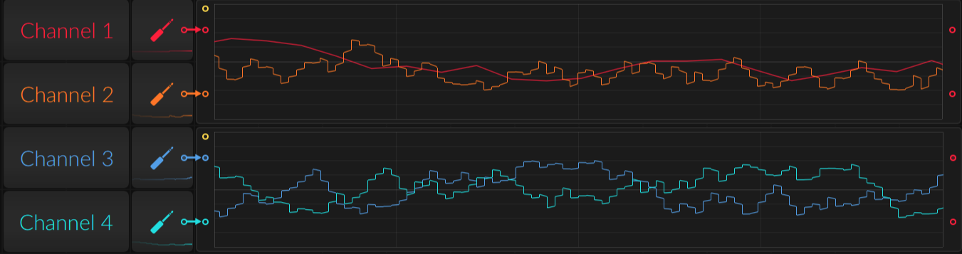
Testing out LFO alternate mode, I tried out the same setup as in my last example [Channels 1-4 chained in LFO mode (flashing magenta) and having Channel 1 trigger as the clock input (unlit) with Channels 2-4 set to Trigger Link (red)]. For this I also have the SHAPE (SLEW) turned fully counterclockwise for all channels.
With Channels 1-4 RISE knob set to noon position Channels 2-4 respond to the incoming clock coming from the Channel 1 Trig input, but the Channel 1 rate of change does not respond at all to changes in the incoming clock. (as shown in screenshot below).
Also, the turning RISE knob counterclockwise for any channels does not have any response to clock division, but does appear to work for clock multiplication on channels 2-4.
Quadrax can be set to ±10v or ±5v. Assuming that’s a software and not a hardware limitation, is there a possibility of a 0-1v setting for use with LZX video modules?
You can also assign a Single CV input to level on each channel and put a steady 1V signal there. Set the module to 5v envelopes for it to work across all modes
Would just like to add my support for linking the gate rather than trigger when in AHR mode.
Just spent a few minutes looking very confused trying to work out why I couldn’t get the 1st channel to be a held volume envelope with a 2nd channel being a held filter envelope.
I was scratching my head over the same thing this past weekend.
Couldn’t find anything that showed we had the ability to linking gates in previous firmware versions, but I could of swore we could do that before…
Thanks @kamil for the update… that’s good news.
Thanks for the firmware updates! I was surprised to see that Quadrax was getting more features, this is exciting!
Just to confirm an earlier report: I had the same issue as Minatorymodular and channel 2 wasn’t outputting voltage, the light wasn’t coming on either. I wonder why channel 2 is the one that freaks out? I tried to see if clearing just the CV assignments would fix it, but no luck, however the full system reset did the trick and everything seems fine now.
Is there going to be a way to chain Quadrax in the future and really use that spare I2C port?